

Micro Hardness Testers: A Comprehensive Technical Guide
Introduction
Micro hardness testing represents a critical capability in materials science and quality control, enabling precise characterization of mechanical properties at microscopic scales. Unlike macro hardness tests that apply loads exceeding 10 Newtons (N), micro hardness testers operate with forces ranging from 0.0098 N to 9.8 N (1 gf to 1000 gf), making them essential for evaluating thin films, surface coatings, and delicate microstructures that would be destroyed by conventional testing methods
.
This comprehensive guide examines the principles, methodologies, instrumentation, and applications of micro hardness testing technology.
Fundamental Principles
Definition and Scope
Micro hardness testing is defined as indentation hardness testing involving applied loads of 1 N or less, or more precisely, tests resulting in indentation depths of less than 70–100 μm
. The fundamental principle involves pressing a diamond indenter of specific geometry into a material surface under controlled load for a defined dwell time, then measuring the resulting indentation to calculate hardness values
.
The microindentation hardness number is calculated by dividing the applied force by either the surface area (Vickers) or projected area (Knoop) of the permanent impression
. This approach enables characterization of materials at scales impossible with macro hardness methods.
Distinction from Macro Hardness Testing
Table
| Parameter | Macro Hardness Testing | Micro Hardness Testing |
|---|---|---|
| Applied Load | > 10 N (typically 50–3000 kgf) | ≤ 9.8 N (1–1000 gf) |
| Indentation Size | Visible to naked eye | Requires microscopy |
| Sample Requirements | Bulk materials | Thin films, coatings, small components |
| Common Methods | Rockwell, Brinell, Macro-Vickers | Vickers, Knoop microindentation |
| Surface Damage | Significant | Minimal, controlled |
Primary Testing Methods
Vickers Micro Hardness Testing
The Vickers method utilizes a highly polished, pointed, square-based pyramidal diamond indenter with face angles of 136° between opposite faces
. The indenter creates a geometrically similar indentation regardless of load, enabling consistent hardness calculations across different force levels.
Calculation Formula:HV=1.854×d2P
Where:
- P = Applied load in Newtons
- d = Arithmetic mean of the two diagonal lengths in millimeters
Key Characteristics:
- The indentation depth is approximately one-seventh of the average diagonal length
- Suitable for small, rounded samples and general-purpose micro hardness evaluation
- Not recommended for coating thicknesses under 60 microns
- Provides geometrically similar indentations at all test forces
Knoop Micro Hardness Testing
The Knoop method employs a rhombic-based pyramidal diamond indenter with edge angles of 172°30′ and 130°0′
. This elongated geometry produces a diamond-shaped indentation with a long-to-short diagonal ratio of approximately 7:1
.
Calculation Formula:HK=14.229×L2P
Where:
- P = Applied load in Newtons
- L = Length of the longer diagonal in millimeters
Key Characteristics:
- Shallower penetration—approximately half the depth of an equivalent Vickers indentation
- Reduced sample damage compared to Vickers method
- Superior for long, narrow samples and thin coatings
- Enables closer indentation spacing along the short diagonal direction, improving resolution for hardness gradient mapping
Comparative Analysis: Vickers vs. Knoop
Table
| Feature | Vickers | Knoop |
|---|---|---|
| Indenter Geometry | Square-based pyramid (136°) | Rhombic-based pyramid (172.5° × 130°) |
| Indentation Shape | Square | Elongated diamond (7:1 ratio) |
| Penetration Depth | ~d/7 | ~L/30 (shallower) |
| Area Calculation | Surface area | Projected area |
| Best Applications | General micro hardness, small rounded samples | Thin coatings, brittle materials, gradient analysis |
| Indentation Spacing | Standard requirements | Closer spacing possible along short diagonal |
Instrumentation and System Components
Core Machine Architecture
Modern micro hardness testers integrate several precision subsystems:
- Loading System: Frictionless loading shafts with precision force application mechanisms capable of delivering test forces from 0.098 N to 9.807 N (10 gf to 1000 gf)
- Indentation Turret: Manual or motorized turrets housing the diamond indenter and objective lenses. Motorized systems automatically switch between indentation and measurement positions
- Optical Measurement System: High-magnification microscopes (typically 400× to 500×) with calibrated eyepiece micrometers or digital image processing systems
- Sample Positioning: Precision XY stages with minimum measurement units down to 0.1–0.25 μm
Advanced Features
Automated Systems:
- Automatic test force selection and application
- Motorized turret positioning with automatic lens switching
- Digital image analysis with automatic diagonal measurement
- Built-in printers and PC connectivity via RS-232 interfaces
Digital Integration:
- CCD cameras with image processing software
- Automatic hardness calculation and scale conversion
- Data storage and statistical analysis capabilities
Focus Assistance:
- Focus finders to rapidly detect focal position on highly polished samples with minimal surface detail

Standards and Calibration
International Standards
ASTM Standards:
- ASTM E384: Standard Test Method for Microindentation Hardness of Materials—covers Knoop and Vickers indenters under test forces from 9.8 × 10⁻³ to 9.8 N (1 to 1000 gf)
- ASTM E92: Test Methods for Vickers Hardness and Knoop Hardness of Metallic Materials
- ASTM E140: Hardness Conversion Tables for Metals
ISO Standards:
- ISO 6507: Metallic materials—Vickers hardness test (Parts 1-3)
- ISO 4545: Metallic materials—Knoop hardness test
Important Note: The term “microhardness” should be avoided in technical documentation because it implies that the hardness itself is low, rather than the force or indentation size
. The preferred terminology is “microindentation hardness.”
Calibration Requirements
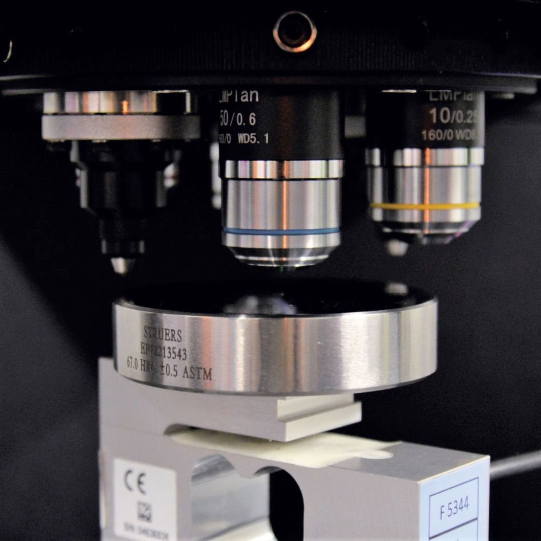
Direct Verification: Testing machines require direct verification and calibration using certified reference hardness test blocks
. Calibration procedures involve:
- Performing multiple indentations on certified reference blocks (typically 10 indentations)
- Comparing measured values against certified values (e.g., 197 ± 6 HV25 against 200 HV25 standard)
- Verifying measurement uncertainty compliance with ISO/IEC 17025 requirements
Test Block Specifications:
- Macro-Vickers (≥HV2): Round blocks, Ø64 mm × 15 mm thick or Ø65 mm × 10 mm thick
- Micro-Vickers (<HV1) and Micro-Knoop: Round blocks, Ø30 mm or Ø40 mm × 10 mm thick
- Certification: UKAS or DAkkS certified blocks traceable to national standards
Calibration Frequency: Regular calibration is essential, with specific intervals determined by usage intensity and quality system requirements. Factors affecting calibration include:
- Applied load accuracy
- Indenter geometry and condition
- Measurement system (microscope) magnification accuracy
- Dwell time control
Sample Preparation and Testing Procedures
Surface Preparation Requirements
Micro hardness testing demands meticulous surface preparation:
- Polishing: Standard metallographic polishing methods required to achieve smooth, scratch-free surfaces
- Roughness Control: Surface roughness variations can cause significant measurement errors
- Cleanliness: Surface contaminants lead to inconsistent indentations
- Vibration Isolation: Testing machines must be isolated from environmental vibrations
Testing Procedure (Vickers Method)
- Sample Mounting: Secure specimen on coordinate anvil or specialized fixture
- Focus: Position sample surface at focal plane using appropriate objective
- Load Selection: Choose test force appropriate for material and coating thickness
- Indentation: Apply load for standard dwell time (typically 10–15 seconds)
- Measurement: Switch to measurement objective and measure both diagonals
- Calculation: Compute HV using standard formula or automated software
Critical Testing Considerations
Indentation Spacing: To ensure accurate measurements, indentations must be spaced sufficiently apart to avoid work hardening effects from adjacent tests
.
Load Selection: The test load must be chosen such that indentation dimensions are measurable while not penetrating through thin coatings or surface layers
.
Elastic Recovery: The calculation assumes the indentation does not undergo elastic recovery after force removal
.
Applications and Industry Use Cases
Primary Application Areas
Surface Engineering:
- Carburizing and nitriding depth verification through hardness traverses on cross-sections
- Case hardening layer thickness determination
- Coating hardness evaluation (electroplated layers, PVD/CVD coatings)
Microstructural Analysis:
- Hardness of individual microconstituents in multiphase alloys (e.g., pearlite vs. ferrite in steels)
- Characterization of segregation zones and structural gradients
- Weld joint evaluation through cross-sectional hardness mapping
Precision Components:
- Miniature workpieces too small for macro hardness testing
- Thin foils and wires
- Electronic components and semiconductor materials
- Medical device components and implants
Industry-Specific Applications
Table
| Industry | Application | Method |
|---|---|---|
| Automotive | Surface hardness profiling of carburized gears and bearings | Micro-Vickers |
| Aerospace | Ceramic coating characterization on turbine blades | Knoop |
| Electronics | Thin film metal and ceramic characterization | Micro-Vickers (low load) |
| Medical Devices | Coating evaluation on implants; weld zone analysis | Combined methods |
| Tooling | Nitrided layer depth verification | Micro-Vickers traverses |
| Materials Research | Phase hardness in powder metallurgy specimens | Vickers microindentation |
Advanced Techniques and Emerging Technologies
Depth-Sensing Indentation (DSI)
Modern micro hardness systems incorporate depth-sensing capabilities that continuously measure load versus displacement during indentation. This enables:
- Continuous stiffness measurement
- Elastic modulus determination alongside hardness
- Investigation of indentation size effects
Reference Point Indentation (RPI)
A specialized depth-sensing technique using two coaxial probes—an inner indenting probe and an outer reference probe resting on the adjacent surface. RPI offers:
- In vivo testing capability (simplified surface preparation)
- Multiple indentation cycles for studying time-dependent deformation
- Indentation Distance Increase (IDI) measurement for local post-yield behavior characterization
Automated and Smart Systems
Contemporary micro hardness testers feature:
- Automatic test point positioning with high-precision XY stages
- Pattern programming for grid-based hardness mapping
- Statistical process control integration
- Hardness conversion between HV, HK, HB, HRC, and other scales per ASTM E140
Selection and Purchasing Considerations
Key Selection Criteria
When selecting a micro hardness tester, evaluate:
- Test Force Range: Ensure coverage from 10 gf to 1000 gf for ASTM E384 compliance
- Measurement Resolution: Minimum units of 0.1–0.25 μm for precise diagonal measurement
- Automation Level: Manual turret vs. motorized systems based on throughput requirements
- Software Integration: Digital image analysis, data management, and statistical capabilities
- Standard Compliance: Verification of ASTM E384, ISO 6507, and ISO 4545 conformance
Quality Verification
- Request sample test reports demonstrating measurement accuracy and repeatability
- Verify calibration processes and quality control checkpoints
- Confirm indenter certification and traceability
- Evaluate optical system magnification accuracy
Conclusion
Micro hardness testers represent essential instrumentation for modern materials characterization, bridging the gap between bulk mechanical property testing and nanoscale indentation techniques. The Vickers and Knoop methods provide complementary capabilities—Vickers offering geometric similarity and universal applicability, while Knoop excels in shallow penetration and gradient analysis applications.
As manufacturing technologies advance toward micro-scale features, surface-engineered components, and thin functional coatings, the importance of precise micro hardness characterization continues to grow. Modern systems integrating automation, digital image analysis, and depth-sensing capabilities enable unprecedented efficiency and accuracy in quality control and research applications.
Understanding the principles, standards, and proper operational procedures outlined in this guide enables materials engineers and quality professionals to leverage micro hardness testing effectively for ensuring product performance and reliability across diverse industrial sectors.