

The Universal Standard: A Complete Guide to the Rockwell Hardness Tester

Introduction: The 100-Pound Legacy
In the vast landscape of mechanical testing, few instruments have achieved the ubiquity of the Rockwell hardness tester. Walk into any heat treatment shop, quality assurance lab, or failure analysis facility, and you will find one. Its distinctive dial, spring-loaded lever, and satisfying “clunk” are as familiar to metallurgists as a stethoscope is to a physician.
Why this machine, above all others? Because the Rockwell test is fast, direct-reading, and nondestructive. Unlike Vickers or Brinell tests, which require measuring indent diagonals with an optical microscope, Rockwell gives a hardness number in seconds, directly on a dial or digital display. This simplicity has made it the workhorse of industry for over a century.
This article explores the Rockwell tester in depth: how it works, how to operate it correctly, how to select the proper scale, and how to interpret results according to international standards.
1. A Brief History: The Wilson Innovation
The Rockwell test was invented in 1914 by Hugh M. Rockwell and Stanley P. Rockwell (cousins) in Waterbury, Connecticut. At the time, Brinell testing was standard, but it left large, visible indentations and required a microscope to measure. The Rockwells sought a method that would:
- Produce a small indentation
- Give an immediate numerical reading
- Be insensitive to operator skill in measurement
Their solution was a depth-sensing instrument. Instead of measuring indentation diameter, they measured indentation depth under load. The first commercial Rockwell tester was produced by the Wilson Mechanical Instrument Company in 1920. Today, the Rockwell test is defined by ASTM E18 (USA) and ISO 6508 (international), and the legacy of the Rockwell name lives on in every tester manufactured worldwide.
2. Fundamental Principle: Depth of Penetration
Unlike other hardness tests that measure indentation area, the Rockwell test measures indentation depth. The principle is elegantly simple:
- An indenter (either a diamond cone or a steel ball) is forced into the specimen under a minor load (typically 10 kgf). This seats the indenter and establishes a reference depth (zero point).
- A major load (ranging from 60 kgf to 150 kgf) is added, forcing the indenter deeper.
- The major load is removed, returning to the minor load.
- The permanent increase in depth (the residual indentation) is measured. This depth increment is converted into a Rockwell hardness number.
The relationship is inverse: A harder material produces a shallower permanent indentation, therefore a higher Rockwell number.
The dial or display is calibrated so that one unit on the Rockwell scale equals 0.002 mm (2 microns) of permanent depth. The formula differs by scale, but conceptually:HR=Constant−Permanent Depth (mm)0.002 mmHR=Constant−0.002 mmPermanent Depth (mm)
For the Rockwell C scale (diamond indenter, 150 kgf major load), the constant is 100. Thus, a very hard material (e.g., 65 HRC) has a permanent depth of (100-65) × 0.002 mm = 0.07 mm. A softer material (e.g., 30 HRC) has a depth of (100-30) × 0.002 mm = 0.14 mm.
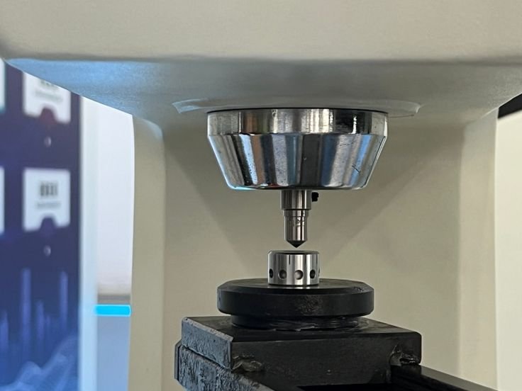
3. The Anatomy of a Rockwell Tester
A standard bench-top Rockwell tester consists of several key components:
| Component | Function |
|---|---|
| Indenter | Diamond cone (120° apex, 0.2 mm tip radius) for hard materials; tungsten carbide ball (1/16″, 1/8″, 1/4″, 1/2″) for soft materials |
| Anvil | Specimen support table (flat, V-notch, or custom shape) |
| Elevating screw | Raises the specimen into contact with the indenter |
| Minor load mechanism | Applies 10 kgf (or 3 kgf for superficial) via a deadweight or spring |
| Major load mechanism | Applies 60, 100, or 150 kgf via additional deadweights |
| Depth measurement system | Dial gauge, LVDT (linear variable differential transformer), or optical encoder |
| Dashpot (oil reservoir) | Controls loading rate to prevent impact |
| Cycle lever / start button | Engages the major load sequence |
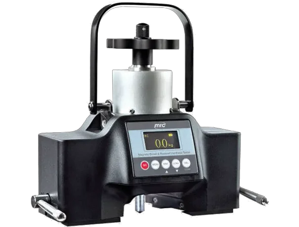
Modern digital testers replace the dial with a digital readout, store data, and can output to a printer or LIMS (laboratory information management system). However, the mechanical principle remains unchanged.

4. Rockwell Scales: The Alphabet of Hardness
One tester, many scales. The Rockwell system uses different combinations of indenter type and major load to cover materials from soft plastics to cemented carbides. The scale is denoted by a letter: HRC, HRB, HRA, HR15N, etc.
4.1 Common Rockwell Scales (ASTM E18 / ISO 6508)
| Scale | Indenter | Major Load (kgf) | Typical Application | Usual Range |
|---|---|---|---|---|
| HRC | Diamond (120°) | 150 | Hardened steels (>30 HRC), tool steels, bearing races | 20–70 HRC |
| HRB | 1/16″ ball | 100 | Soft to medium steels (annealed), brass, aluminum alloys | 20–100 HRB |
| HRA | Diamond | 60 | Very hard thin materials (carbides, shallow case-hardened layers) | 60–85 HRA |
| HRD | Diamond | 100 | Medium-hard steels (between C and B ranges) | 40–77 HRD |
| HRE | 1/8″ ball | 100 | Bearing metals, very soft alloys | 70–100 HRE |
| HRF | 1/16″ ball | 60 | Thin soft metals (annealed copper, thin brass) | 60–100 HRF |
| HR15N (Superficial) | Diamond | 15 | Thin cases, small parts, plated surfaces | 80–92 HR15N |
4.2 Superficial Rockwell Scales
For thin specimens (≤0.25 mm) or shallow case depths (<0.5 mm), the standard Rockwell loads would punch through. Superficial testers use:
- Minor load: 3 kgf (instead of 10 kgf)
- Major loads: 15, 30, or 45 kgf
- Scales: N (diamond), T (1/16″ ball), W, X, Y (larger balls)
Example: HR15N is used for carburized cases 0.15–0.30 mm deep.
4.3 Scale Selection Rules of Thumb
- Hardened steel → HRC (aim for 20–70 range; below 20 HRC, switch to HRB)
- Annealed steel, brass, soft aluminum → HRB
- Very hard (>70 HRC) or very thin → HRA
- Plastics, lead, bearing babbit → HRE, HRF, or HRR
- Case-hardened parts → HRN (superficial)
Critical rule: Never use a scale that produces an indentation deeper than 1/10th of the specimen thickness. For HRC on steel, minimum thickness is approximately 1.5 mm. For HRB on brass, minimum is 2 mm.
5. Step-by-Step Operation (Analog Tester)
Despite digital automation, understanding the manual sequence is essential for troubleshooting.
Step 1: Select and install the correct indenter (diamond for HRC, ball for HRB). Secure it in the spindle.
Step 2: Select the major load by adjusting the deadweight hanger (60, 100, or 150 kgf).
Step 3: Select the appropriate anvil. Use a flat anvil for flat specimens, a V-anvil for cylindrical parts (to prevent rolling).
Step 4: Zero the dial. With no load, rotate the dial so the “set” pointer aligns with the “0” (for diamond) or “30” (for ball scales—this preloads the dial mechanism).
Step 5: Apply the minor load. Raise the specimen using the elevating screw until the small pointer indicates the “set” position (typically a line or dot on the dial). The minor load (10 kgf) is now applied.
Step 6: Zero the major-load dial. Turn the bezel so the “0” on the large scale aligns with the long pointer.
Step 7: Apply the major load. Pull the cycle lever (or press the start button). The load is applied via a dashpot-controlled descent. Wait for the pointer to come to a complete stop (usually 4–6 seconds).
Step 8: Remove the major load. Push the lever back. The major load releases, but the minor load remains. The dial now indicates the Rockwell hardness number directly.
Step 9: Read the value. For diamond indenters, read the black numbers (typically 0–100). For ball indenters, read the red numbers (typically 20–100). Record as, e.g., “62 HRC” or “85 HRB.”
Step 10: Lower the specimen and remove. Rotate the elevating screw counterclockwise. Move to the next test location (ensure at least 3 indentation diameters from any previous indent).
6. Specimen Preparation and Requirements
Rockwell testing is relatively forgiving, but certain conditions must be met.
6.1 Surface Finish
- For HRC: 0.8 µm Ra (32 µin) or better. Ground or polished surface.
- For HRB: 1.6 µm Ra (63 µin) acceptable.
- Do not test on as-forged, as-cast, or heavily scaled surfaces—the indenter will seat inconsistently.
6.2 Thickness
Minimum thickness = 10× the indentation depth. For HRC on steel, depth ≈ 0.08–0.15 mm, so minimum thickness ≈ 0.8–1.5 mm. If an indent causes a bulge on the opposite side, the specimen is too thin.
6.3 Flatness and Parallelism
The test surface must be perpendicular to the indenter axis. For small cylindrical parts (e.g., rods <6 mm diameter), use a V-anvil and correct for curvature per ASTM E18 correction tables (typically subtract 0.5–2.5 HRC for small diameters).
6.4 Lateral Support
Thin sheets must be backed with a solid support of equal or greater hardness to prevent bending. Glue the specimen to a steel block if necessary.
7. Verification and Calibration
A Rockwell tester is only as good as its last calibration. ASTM E18 and ISO 6508 require regular verification using certified test blocks (directly traceable to a national metrology institute).
7.1 Daily Verification (Operator Check)
- Test a certified block of known hardness (e.g., 60 HRC) with five indents.
- Average must be within ±1.5 HRC of the block’s certified value for regular scales (HRC, HRB), or ±1.0 HRC for superficial scales.
- Standard deviation (repeatability) must be ≤0.5 HRC.
7.2 Annual Calibration (Service Technician)
- Complete load cell verification
- Indenter geometry inspection (diamond tip radius, ball diameter)
- Depth measurement system linearity
- Loading rate (dashpot timing)
- Cycle timing
7.3 Common Calibration Failures and Causes
| Symptom | Likely Cause |
|---|---|
| Readings consistently high (e.g., 63 vs 60) | Worn diamond indenter (flattened tip) |
| Readings consistently low | Oil in dashpot too viscous (slow loading); or indenter loose |
| Poor repeatability (scatter >1 HRC) | Loose spindle bearings; dirty depth measuring mechanism; specimen not seated |
| Different results on different anvils | Anvil not flat; dirt on anvil surface |
| Drifting reading during major load hold | Hydraulic leak in dashpot or worn seals |
8. Advantages and Limitations
Advantages:
- Direct reading – no microscope, no calculation.
- Fast – 10–15 seconds per test.
- Nondestructive – small indent (typically <0.5 mm diameter).
- Versatile – multiple scales cover 20 to 70 HRC and soft materials.
- Portable options available (bench-top testers are standard, but portable Rockwell-like testers exist for large parts).
Limitations:
- Not a true scientific measurement – the inverse depth relationship is arbitrary and scale-specific.
- Subject to anvil and surface effects – more sensitive to surface condition than Vickers.
- Limited for thin or curved parts – requires correction tables or superficial scales.
- Indentation depth varies with modulus – Rockwell numbers for plastics and metals are not directly comparable.
- Operator dependent – inconsistent zeroing or loading rate affects results.
9. Common Errors and Troubleshooting
| Operator Error | Consequence | Solution |
|---|---|---|
| Raising specimen too fast | Overshoots minor load, false zero | Use slow, steady screw motion |
| Not waiting for pointer to stop | Reads before full creep has ended | Wait 2–3 seconds after pointer stops |
| Testing near edge or previous indent | Low reading (edge flow) or high reading (work hardening) | Keep indent ≥3 diameters from edge and prior indents |
| Using wrong scale (e.g., HRC on annealed steel) | Indenter penetrates too deep (off-scale low) | Switch to HRB or HRE |
| Dirty anvil or indenter | Poor repeatability | Clean with alcohol; inspect for debris |
| Cylindrical part not using correction | Error up to 4 HRC | Apply correction from ASTM E18 Table 2 |
10. Rockwell vs. Other Hardness Tests
| Property | Rockwell | Vickers | Brinell |
|---|---|---|---|
| Measurement | Depth | Diagonal length | Diameter |
| Speed | Fast (seconds) | Slow (minutes, plus microscope) | Slow (needs microscope or optical scanner) |
| Operator skill | Low | High | Medium |
| Indent size | Very small (0.1–0.5 mm) | Small (0.05–0.3 mm) | Large (1–6 mm) |
| Best for | Production QC, heat treat verification | Research, thin sections, case depth | Large castings, inhomogeneous materials |
| Standards | ASTM E18, ISO 6508 | ASTM E92, ISO 6507 | ASTM E10, ISO 6506 |
11. Special Applications
11.1 Hardness Testing of Welds (Rockwell Limitations)
As noted in the previous article on weld hardness testing, Rockwell is not suitable for measuring HAZ hardness because the indenter averages over multiple zones. Use Vickers microhardness instead.
11.2 Case Depth Screening
For shallow cases (<0.5 mm), use superficial Rockwell (HR15N, HR30N). However, this only indicates surface-near hardness; it does not give case depth. For that, a microhardness traverse is still required.
11.3 Plastics and Elastomers
Special Rockwell scales for plastics (e.g., HRR, HRL, HRM) use larger balls (1/2″) and lower loads. However, plastics exhibit time-dependent creep, so the reading changes with dwell time. Standardized dwell times (15 seconds) are critical.
11.4 Portable Rockwell Testers
For large parts (e.g., pipes, rails, large dies), portable testers like the Telebrineller or the King Portable Rockwell use a clamp-on mechanism. They are less accurate (±2 HRC) but invaluable for field work.