



Micro hardness tester: 9 Powerful Applications for Precision Surface and Material Analysis


What Is a Micro Hardness Tester?
A mikrotvrdomer is a precision instrument designed to measure the hardness of very small areas, thin sections, surface layers, coatings, and individual regions within a material.
Unlike conventional hardness testing, which often produces a relatively large indentation, microhardness testing uses a much smaller test force. The resulting indentation can therefore be tiny enough to fit within a thin layer or a specific region of a metallographic specimen.
The method is widely used in:
- Metallurgical laboratories
- Heat-treatment plants
- Výskum a vývoj
- Automotive manufacturing
- Aerospace manufacturing
- Tool and die production
- Coating development
- Welding laboratories
- Analýza porúch
- Quality-control laboratories
A typical instrument combines a precision loading system with a high-resolution optical microscope or camera.
The tester applies a controlled force through a diamond indenter. After the force is removed, the indentation is examined and measured. Software then calculates the hardness value.
Modern systems can also automate indentation placement, optical measurement, hardness calculations, statistical analysis, and reporting.
How Microhardness Testing Works
Microhardness testing is usually based on either the Vickers alebo Knoop indentation method.
The instrument applies a small, controlled force to the specimen. Because the force is relatively low, the indentation can be extremely small.
This allows engineers to measure hardness in locations that would be impossible to evaluate accurately using a large indentation.
For example, suppose a steel component has a hardened surface only a fraction of a millimeter deep. A conventional hardness indentation could extend beyond the treated layer.
A microhardness test, however, can place a series of small indentations from the surface toward the core.
The result is a detailed hardness profile.
Why Small Indentations Matter
Small indentations provide much greater spatial resolution.
This is valuable when the material changes over a short distance.
Examples include:
- Case-hardened steel
- Nitrided surfaces
- Plated coatings
- Zóny ovplyvnené teplom pri zváraní
- Tenké plechy
- Individual phases
- Diffusion layers
- Powder-metallurgy materials
The ability to measure localized hardness is one of the main reasons microhardness systems are so important in materials research and industrial quality control.
Vickers and Knoop Microhardness Testing
Two indentation methods are especially common in microhardness applications: Vickers a Knoop.
Vickers Diamond Indenter
The Vickers indenter is a square-based diamond pyramid.
After testing, the indentation has an approximately square shape, and the two diagonals are measured.
Vickers testing is widely used for:
- Metals
- Heat-treated surfaces
- Welds
- Tenké rezy
- Nátery
- Metalografické vzorky
The Vickers method provides a versatile hardness measurement over a broad range of materials and test forces.

Knoop Diamond Indenter
The Knoop indenter creates a much more elongated indentation.
This geometry can be advantageous when testing very thin materials or narrow regions because the indentation can be made with a relatively small depth.
Knoop testing is commonly considered for:
- Tenké povlaky
- Krehké materiály
- Glass
- Ceramics
- Small surface regions
- Microstructural studies
The choice between Vickers and Knoop should be based on the material, thickness, test objective, and applicable standard.
How a Microhardness Test Is Performed
A successful microhardness test begins with proper sample preparation.
The specimen is usually mounted securely and prepared to provide a smooth, flat testing surface.
The general procedure is:
- Prepare the specimen surface.
- Mount the sample if required.
- Select Vickers or Knoop testing.
- Choose the appropriate test force.
- Position the specimen under the objective.
- Apply the indentation load.
- Maintain the required dwell time.
- Remove the load.
- Locate the indentation.
- Measure its dimensions.
- Calculate the hardness.
- Record and analyze the result.
The smaller the indentation, the more important the quality of the optical system becomes.
Selecting the Test Force
Test force must be selected carefully.
A very low force can produce an indentation that is difficult to resolve. A force that’s too high can make the indentation too large for a thin layer or cause interaction with nearby features.
The ideal force should produce a clearly measurable indentation while preserving the purpose of the test.
Factors include:
- Material hardness
- Layer thickness
- Stav povrchu
- Test area
- Expected hardness
- Mikrostruktúra materiálu
- Required spatial resolution
For hardness-profile testing, the selected load should remain consistent unless the procedure specifically requires otherwise.
Measuring Small Indentations
Microhardness measurement often relies on an optical microscope or digital camera.
A high-quality optical system needs to resolve the indentation corners or edges clearly.
Digital image analysis can help identify the indentation and calculate its dimensions.
However, automated measurement is only as reliable as the image itself.
Poor polishing, glare, scratches, contamination, vibration, or unclear indentation edges can all reduce measurement quality.
Where Microhardness Testing Is Used
Microhardness equipment is particularly useful when conventional hardness testing can’t provide enough spatial resolution.
Heat-Treated and Case-Hardened Materials
Heat treatment often produces hardness changes across a component.
For example, carburizing creates a hardened surface layer while retaining a tougher core.
Microhardness testing can measure hardness at multiple depths.
A typical hardness profile might include measurements at:
- Surface
- Near-surface region
- Transition zone
- Intermediate depth
- Core
Plotting these values creates a hardness-versus-depth curve.
This information can help manufacturers evaluate case depth and treatment consistency.
Nitrided, induction-hardened, and other surface-treated components can also benefit from this approach.
Coatings and Thin Surface Layers
Coatings can be much thinner than the indentation created by conventional hardness methods.
Microhardness testing allows engineers to evaluate selected coatings and thin layers when the test force and procedure are appropriate.
Potential applications include:
- Plated coatings
- Povlaky nanášané termickým nástrekom
- Hard coatings
- Povrchové úpravy
- Thin metallic layers
- Diffusion coatings
Care must be taken to prevent the indentation from extending through the coating and into the substrate.
Welds and Heat-Affected Zones
Welding can create several different material regions:
- Zvarový kov
- Fusion zone
- Heat-affected zone
- Base metal
Their hardness can vary considerably.
A microhardness traverse across a weld cross-section can reveal these changes.
This makes microhardness testing useful for:
- Welding procedure qualification
- Analýza porúch
- Heat-treatment studies
- Metalurgický výskum
- Process optimization
The resulting hardness map can provide much more detail than a single bulk hardness value.
Materials Suitable for Microhardness Testing
Microhardness methods can be applied to many materials when suitable procedures are used.
Steel, Aluminum, Copper, and Titanium
Common engineering applications include:
Steel
- Nástrojové ocele
- Stainless steels
- Carburized steels
- Nitrided steels
- Welded steels
Aluminum
- Tepelne spracované zliatiny
- Aerospace alloys
- Coated components
Copper
- Electrical materials
- Zliatiny medi
- Processed sheet materials
Titanium
- Aerospace components
- Biomedical materials
- Surface-treated parts
Because these materials can have different microstructures and elastic-plastic behavior, test conditions should always be selected according to the applicable method.
Ceramics and Specialized Materials
Microindentation techniques can also be valuable for certain ceramics, glass, hard coatings, and advanced engineering materials.
However, brittle materials may respond differently from ductile metals.
Cracking around the indentation can influence measurement and interpretation.
For specialized materials, users should follow a method specifically applicable to that material rather than assuming that a standard metal-testing procedure is automatically valid.
Microhardness Testing for Hardness Profiles
One of the most powerful applications is hardness mapping.
Instead of taking one measurement, the operator places multiple indentations at defined positions.
Napríklad:
Surface → 0.05 mm → 0.10 mm → 0.20 mm → 0.30 mm → Core
The resulting data can show how material properties change with depth.
This is particularly useful for:
- Case-hardening analysis
- Nitriding studies
- Indukčné kalenie
- Weld evaluation
- Coating characterization
- Diffusion research
Automated systems can make this process much faster.
An operator can define a test line or pattern, and the machine can automatically move between measurement positions.
The resulting hardness profile can then be exported into a report or analyzed with laboratory software.
Factors That Affect Microhardness Accuracy
Because microhardness indentations are small, tiny errors can have a noticeable effect on the final result.
Important factors include:
- Drsnosť povrchu
- Polishing quality
- Indenter geometry
- Test-force accuracy
- Čas zdržania
- Optical resolution
- Specimen alignment
- Vibration
- Indentation spacing
- Edge distance
- Technika obsluhy
Príprava povrchu
Surface preparation is arguably one of the most important parts of microhardness testing.
A rough surface can obscure indentation edges.
A scratch that would be insignificant during a conventional hardness test may be large compared with a microhardness indentation.
For metallographic work, samples may require several stages of grinding and polishing.
The final preparation should produce a sufficiently flat and clean surface without altering the region that needs to be measured.
Vibration, Alignment, and Indenter Condition
Microhardness machines are sensitive to mechanical stability.
Nearby machinery, unstable tables, vibration, or specimen movement can influence the indentation or optical measurement.
The indenter must also remain in good condition.
A damaged or worn diamond can change indentation geometry and introduce systematic measurement errors.
For high-precision laboratories, environmental stability and routine verification should therefore be treated as part of the measurement system.
Microhardness vs Conventional Hardness Testing
The main difference is measurement scale and application.
| Method | Typical Strength | Typické použitie |
|---|---|---|
| Mikrotvrdosť | Very small test areas | Thin layers and local regions |
| Vickers | Flexible indentation testing | Laboratory material testing |
| Rockwell | Fast depth measurement | Production QC |
| Brinell | Large indentation | Castings and coarse materials |
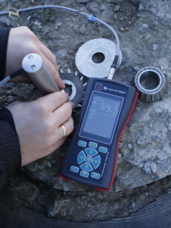
| Leeb | Portable rebound testing | Large field components |
Microhardness testing is the better choice when location matters.
If the question is simply “How hard is this bulk component?”, Rockwell or Brinell may be more practical.
If the question is “How does hardness change across this 0.2 mm surface layer?”, microhardness is much more appropriate.
In other words, the method should follow the inspection question.
Standards, Calibration, and Verification
A reliable laboratory needs a documented verification process.
Vickers and Knoop microindentation hardness testing are covered by recognized ASTM and ISO standards, depending on the specific application and force range.
Stránka ISO 6507 series provides requirements for Vickers hardness testing of metallic materials, while ASTM publishes standards covering Vickers and Knoop microindentation hardness testing.
Users should always verify the current standard edition and ensure that the chosen procedure applies to the material and test range.
Verification can involve:
- Test-force checks
- Indenter geometry checks
- Optical measurement checks
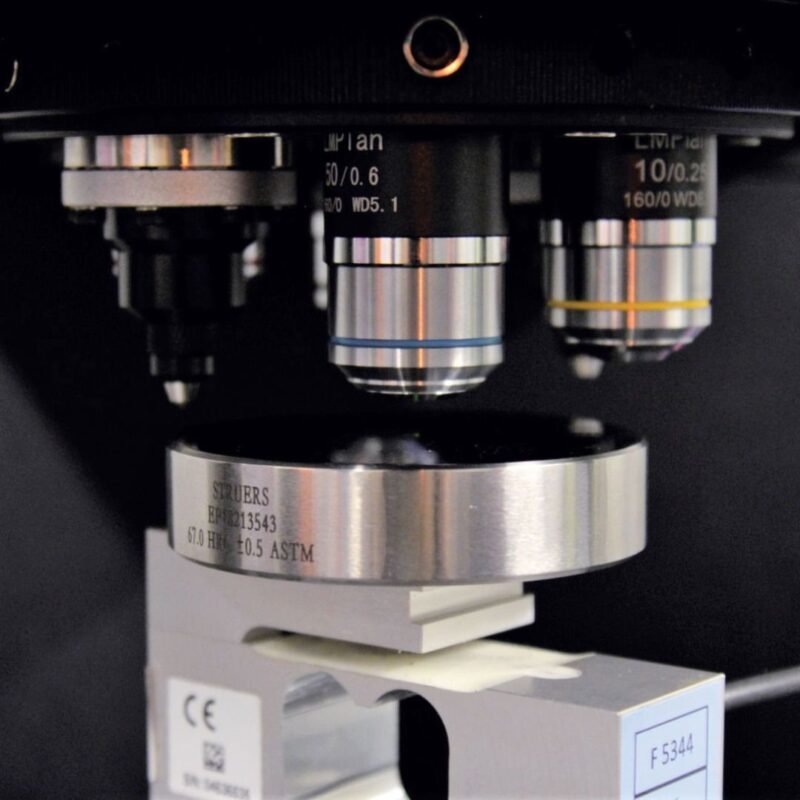
- Reference hardness blocks
- Repeatability evaluation
- Calibration documentation
Microhardness Reference Blocks
Certified reference materials help confirm that the complete testing system remains within acceptable performance limits.
Records should identify:
- Reference block
- Certified value
- Certificate
- Tester
- Indenter
- Test force
- Date
- Verification result
This traceability becomes especially important in accredited laboratories and customer-regulated manufacturing environments.
Manual, Digital, and Automatic Microhardness Systems
Manual Systems
Manual systems require the operator to position the specimen and usually measure the indentation through an optical microscope.
They’re suitable for basic laboratory applications and lower testing volumes.
Digital Systems
Digital systems combine optical imaging with electronic test control.
Typical features include:
- Digital microscope
- Camera
- Automatický výpočet tvrdosti
- Ukladanie obrázkov
- Multiple test forces
- Export údajov
- Test-result management
Automatic Microhardness Systems
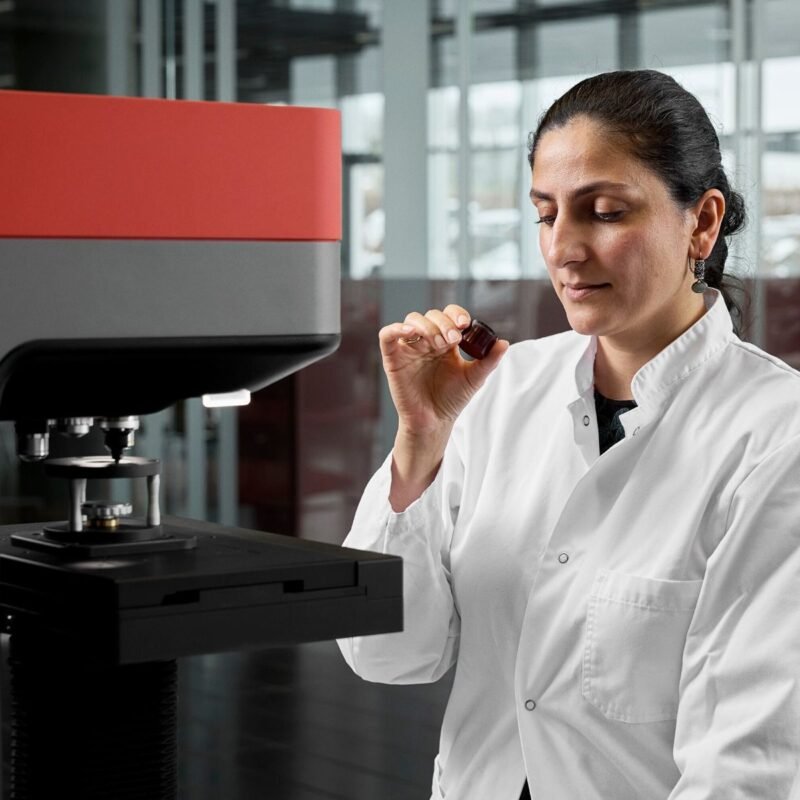
Advanced equipment can automate indentation and measurement.
This is useful when performing:
- Hardness traverses
- Case-depth studies
- Weld mapping
- Large numbers of indentations
- Research experiments
Automation can improve productivity and reduce operator-to-operator differences.
How to Choose the Right Microhardness Tester
Before purchasing equipment, define your testing application first.
Load Range, Optics, Automation, and Software
Load range:
Select a system capable of applying the forces required for your samples.
Optical resolution:
This is critical for very small indentations.
Vickers/Knoop capability:
If your laboratory handles different materials, supporting both methods can provide greater flexibility.
Specimen capacity:
Check the maximum sample dimensions and available fixtures.
Automatic measurement:
Useful for high-volume testing and hardness traverses.
Motorized stage:
A motorized X-Y stage can simplify automated mapping.
Software:
Look for image analysis, hardness calculations, data storage, report generation, and export functions.
Calibration support:
Make sure reference blocks, indenters, and service support are readily available.
For broader laboratory inspection requirements, manufacturers can also review industrial hardness testing equipment.
Hardness Mapping and Case-Depth Analysis
If your laboratory performs advanced metallurgical testing, automated mapping can be a major productivity advantage.
The system can place multiple indentations according to a predefined pattern and generate a hardness profile.
This can reduce manual positioning and make test procedures easier to reproduce.
Common Microhardness Testing Mistakes
Testing on a Poorly Prepared Surface
Even small scratches can interfere with indentation measurement.
Using Too Much Test Force
An indentation that’s too large can overlap adjacent features or penetrate beyond a thin layer.
Using Too Little Force
An extremely small indentation can be difficult to measure accurately.
Ignoring Vibration
Small indentation testing requires a stable test environment.
Testing Too Close to Another Indentation
Nearby indentations can influence each other.
Ignoring Edge Effects
Indentations placed too close to specimen edges can produce unreliable results.
Using a Damaged Indenter
Indenter geometry directly affects hardness calculations.
Relying Completely on Automatic Image Analysis
Software is helpful, but unclear or defective indentation images still require operator judgment.
Skipping Verification
Regular verification is essential for maintaining confidence in laboratory results.
Často kladené otázky
1. What is a micro hardness tester used for?
It is used to measure hardness in very small material regions, thin layers, coatings, weld zones, case-hardened surfaces, and metallographic specimens.
2. What is the difference between microhardness and regular hardness testing?
Microhardness uses much smaller test forces and produces smaller indentations. This allows localized hardness measurement that conventional methods may not provide.
3. Is microhardness testing destructive?
The method creates a small permanent indentation, so it is technically an indentation test rather than completely non-destructive. The small mark is often acceptable for laboratory specimens and selected components.
4. What is the difference between Vickers and Knoop testing?
Vickers uses a square-based diamond pyramid and measures two indentation diagonals. Knoop uses an elongated diamond indenter and is particularly useful for thin layers and small regions.
5. Can microhardness testing measure coatings?
Yes, when the coating thickness, test force, indentation size, and substrate effects are properly controlled.
6. Can it measure the hardness of a weld?
Yes. Microhardness traverses are commonly used to evaluate hardness changes across weld metal, heat-affected zones, and base material.
7. Can microhardness testing determine case depth?
Yes. A series of hardness measurements from the surface toward the core can be used to characterize a hardness gradient and, when the applicable specification defines the criterion, determine effective case depth.
8. How important is surface preparation?
Extremely important. Because the indentation is small, scratches, roughness, contamination, and poor polishing can significantly affect measurement.
9. How accurate is microhardness testing?
High-quality results are possible when the instrument, indenter, test force, optical system, specimen preparation, environment, and procedure are properly controlled and verified.
10. What should I consider when buying a microhardness system?
Consider the load range, Vickers/Knoop capability, optical resolution, automatic measurement, motorized stage, specimen capacity, software, hardness mapping functions, calibration support, and after-sales service.
Záver
Microhardness testing provides a level of localized material analysis that conventional hardness methods often can’t match.
A properly configured mikrotvrdomer can measure tiny regions of steel, aluminum, copper, titanium, coatings, welds, heat-treated surfaces, and other engineering materials.
Its greatest value comes from situations where hardness changes over a short distance. Instead of producing one broad measurement, the operator can create a detailed hardness profile across a surface layer, weld, coating, or microstructural region.
For manufacturers and laboratories, this can support heat-treatment verification, case-depth analysis, coating development, welding evaluation, metallurgical research, and failure investigation.
Still, precision doesn’t come from the machine alone. Good surface preparation, correct test-force selection, proper specimen mounting, stable environmental conditions, accurate optical measurement, suitable indentation spacing, and regular verification are all essential.
When selecting equipment, focus on the complete testing workflow. A system with the right load range, high-quality optics, Vickers and Knoop capability, automation, mapping software, and reliable calibration support can provide much greater long-term value than a machine chosen only by its purchase price.
For laboratories that need detailed information about localized material behavior, microhardness testing remains one of the most useful tools for modern materials characterization.