


Hardness Testing Machine: Comprehensive Technical Analysis of Equipment, Standards, and Industrial Applications

Introduction
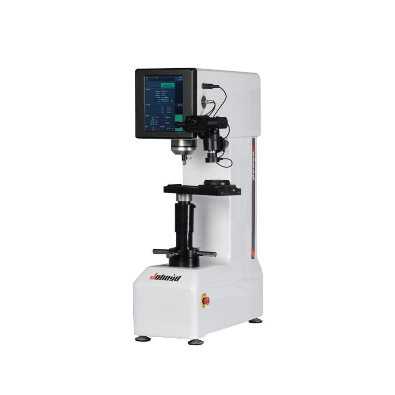
A Hardness Testing Machine is a specialized metrology instrument designed to quantify a material’s resistance to localized plastic deformation through controlled indentation, rebound, or scratch testing methodologies. These machines constitute critical infrastructure in quality control laboratories, manufacturing facilities, and research institutions worldwide, providing essential data for material certification, heat treatment verification, and component reliability assessment
.
Unlike general material testing equipment, hardness testing machines operate on precise mechanical principles governed by international standards including ISO 6506 (Brinell), ISO 6507 (Vickers), ISO 6508 (Rockwell), and ASTM E18/E10/E384. Modern instruments range from manual benchtop units to fully automated robotic systems capable of processing hundreds of specimens with minimal operator intervention
.
Classification and Operating Principles
1. Stationary Benchtop Hardness Testers
Rockwell Hardness Testing Machines
Rockwell testers represent the most prevalent configuration in industrial quality control, utilizing either diamond cone indenters (120° apex angle) or hardened steel balls (1/16″ or 1/8″ diameter)
.
Machine Mechanics:
- Force Application System: Dead-weight or closed-loop load cell mechanisms apply preliminary forces (10 kgf regular, 3 kgf superficial) followed by major forces (60–150 kgf)
- Depth Measurement: Electronic displacement transducers or mechanical dial indicators measure penetration depth differential between preliminary and major loads
- Hardness Display: Direct digital readout or analog scale conversion eliminates manual calculation requirements
Contemporary Rockwell machines feature automated loading cycles ensuring force application “without shock, vibration, or overload” as mandated by ISO 6508-2:2023
.
Brinell Hardness Testing Machines
Brinell machines accommodate high-load testing (500–3000 kgf) utilizing hardened steel or tungsten carbide ball indenters (typically 10 mm diameter)
.
Structural Components:
- Hydraulic or Mechanical Loading: Screw-driven or hydraulic force generation systems
- Optical Measurement Systems: Integrated measuring microscopes or external optical devices measure indentation diameter (typically 2–6 mm)
- Anvil Systems: Specimen support tables capable of vertical adjustment to accommodate test pieces up to 300mm height
ISO 6506-2:2023 specifies that Brinell machines must ensure “the mount holding the ball-holder slides correctly in its guide” and that force application occurs “without shock, vibration, or overrun”
.
Vickers and Knoop Microhardness Testers
These precision instruments utilize diamond pyramid indenters (136° square pyramid for Vickers, rhombic for Knoop) and are essential for microstructural analysis, thin coatings, and surface-hardened components
.
Specialized Features:
- Optical Systems: High-resolution microscopes with 10× to 100× objectives for diagonal measurement
- Load Application: Precision dead-weight systems or electromagnetic loading for forces ranging from 10 gf to 120 kgf
- Automated Image Analysis: Computer-controlled indentation measurement eliminating operator subjectivity
ISO 6507-2:2018 requires verification that “the plunger holding the indenter slides in its guide without friction or excessive side play” and that illumination systems provide “uniform lighting with enough contrast” for precise boundary determination
.
2. Portable Hardness Testing Equipment
Leeb (Rebound) Hardness Testers
Portable Leeb devices utilize dynamic testing principles standardized under ASTM A956 and ISO 16859. These instruments propel a tungsten carbide or diamond-tipped impact body against the test surface, calculating hardness from the rebound velocity ratio .
Equipment Characteristics:
- Integrated Impact Mechanism: Spring-loaded or electromagnetic propulsion systems
- Signal Processing: Piezoelectric sensors capture rebound velocities with microsecond precision
- Material Compensation: Built-in algorithms correct for material elasticity (Leeb hardness is inherently dependent on Young’s modulus)
Ultrasonic Contact Impedance (UCI) Devices
UCI testers following ASTM A1038 employ a Vickers diamond indenter mounted on a resonating rod. The frequency shift resulting from indentation contact correlates directly with material hardness .
Technical Specifications:
- Operating Frequencies: Typically 50–100 kHz resonance
- Minimal Indentation: Nearly non-destructive testing suitable for finished components
- Manual or Motorized Probes: Handheld devices or automated scanning systems
3. Specialized Hardness Testing Systems
Shore Durometers
For elastomers and plastics, Shore hardness machines utilize spring-loaded indenters with calibrated spring forces. ISO 18898:2016 specifies calibration procedures for durometer types A, D, AO, and AM, requiring verification of indenter geometry, spring force, and indentation depth measurement
Automated Robotic Hardness Testing Systems
Advanced manufacturing environments deploy fully automated hardness testing cells featuring:
- Industrial Robots: Handling capacities up to 120 kg for engine blocks, wheel rims, and housing components
- Multi-Method Capability: Modular design allowing switching between Vickers, Rockwell, and Brinell methods
- Integrated Preparation Stations: Automated milling or grinding to ensure surface finish compliance
- Identification and Marking: Camera-based optical character recognition (OCR) followed by automatic component marking
Machine Components and Technical Requirements
Force Generation and Control Systems
Hardness testing machines employ diverse force application mechanisms:表格
复制
| Machine Type | Force Generation Method | Load Range | Precision Requirement |
|---|---|---|---|
| Rockwell | Dead-weight or Load Cell | 15–150 kgf | ±0.5% per ISO 6508-2 |
| Brinell | Hydraulic/Mechanical | 1–3000 kgf | ±1.0% per ISO 6506-2 |
| Vickers | Dead-weight/Electromagnetic | 0.01–120 kgf | ±1.0% per ISO 6507-2 |
Direct Verification Requirements: Standards mandate that force-proving instruments used for calibration must be traceable to national standards (e.g., NIST) with measurement uncertainty incorporated within specified tolerances
.
Indentation Measurement Systems
Optical Measurement: Benchtop Brinell and Vickers machines require integrated measuring microscopes or external optical systems capable of resolving indentation dimensions to ±0.5% accuracy. ISO 6506-2 specifies that illumination systems must not affect diameter measurements and that indentation centers align with the field of view
.
Depth Sensing: Rockwell machines utilize displacement transducers (LVDT or digital encoders) with resolutions of 0.1 µm or better. Machine hysteresis testing verifies that depth measurement systems return to zero repeatability within specified tolerances
.
Environmental and Operational Controls
Calibration standards universally require:
- Temperature Stability: Direct verification performed at (23 ± 5)°C with documentation required for deviations
- Vibration Isolation: Granite or isolated mounting surfaces to prevent external vibration interference
- Specimen Support: Anvil systems ensuring perpendicular indenter contact without overhang or deflection
Calibration, Verification, and Maintenance
Direct Verification Procedures
Direct verification involves independent calibration of machine functional parameters
:
- Force Calibration: Measurement of preliminary and total test forces at minimum three plunger positions using Class 1 force-proving instruments per ISO 376
- Indentation Measurement System: Calibration of optical micrometers or depth sensors using certified gauge blocks or interferometric methods
- Indenter Verification: Direct measurement of indenter geometry (diamond pyramid angles, ball diameter/sphericity) or indirect verification using certified reference blocks
- Testing Cycle Verification: Confirmation of load duration (dwell time) within ±2.0 seconds for Brinell, ±0.5 seconds for Rockwell
Indirect Verification Using Reference Blocks
Indirect verification assesses overall machine performance through standardized hardness blocks
:
- Reference Materials: Certified hardness blocks traceable to national metrology institutes (NIST, PTB, NPL) with values assigned per ISO 6506-3, 6507-3, or 6508-3
- Testing Protocol: Minimum five indentations per block across the machine’s operational range
- Acceptance Criteria: Repeatability and bias calculations per statistical methods defined in ISO standards
- Verification Intervals: Typically 12 months for direct verification, 18–24 months for indirect verification, with daily/weekly monitoring using working reference blocks
Maintenance Protocols
Comprehensive maintenance ensures longevity and accuracy
:
Routine Maintenance:
- Daily cleaning of anvil surfaces and indenter contact points
- Inspection of ball holders for wear or looseness (Brinell)
- Verification of optical system focus and illumination uniformity
Preventive Maintenance:
- Lubrication of mechanical guidance systems (plunger slides, elevating screws)
- Inspection of load application mechanisms for wear or friction
- Electrical system validation for motorized and automated components
Calibration Best Practices:
- Use only one side of reference blocks (front/back hardness may differ)
- Allow machines to stabilize after transportation or environmental changes
- Document all adjustments and establish measurement uncertainty budgets
- Maintain ISO/IEC 17025:2017 accreditation for calibration laboratories
Industry Applications and Selection Criteria
Aerospace and Automotive Manufacturing
Automated hardness testing cells perform 100% inspection of critical components such as crankshafts, camshafts, and landing gear. Robotic systems integrate hardness testing with geometric measurement and surface roughness determination
.
Oil and Gas Infrastructure
Pipeline girth welds and wellhead components require field-portable hardness testing per ISO 15156-2 (NACE MR0175) to verify resistance to sulfide stress cracking. Maximum hardness limits (typically 250 HV or 22 HRC) mandate traceable calibration and qualified testing procedures .
Medical Device Manufacturing
Orthopedic implants undergo microhardness testing (ASTM F746) to verify that surface hardening treatments (plasma nitriding, PVD coatings) enhance wear resistance without compromising corrosion performance .
Material Selection Matrix
表格
复制
| Material/Component | Recommended Machine | Key Considerations |
|---|---|---|
| Bulk steel production | Rockwell (C-scale) | Speed, direct reading, heavy-duty construction |
| Cast iron, coarse grain | Brinell (3000 kgf) | Large ball indenter, optical measurement |
| Thin sheet metal (<0.5mm) | Superficial Rockwell or Micro-Vickers | Low load capability, minimal penetration |
| Surface hardened gears | Vickers cross-section | Precise case depth measurement, autofocus |
| Ceramic coatings | Knoop | Shallow indentation, high magnification |
| Field weld inspection | Portable UCI or Leeb | Battery operation, data logging, minimal prep |
Technological Advancements and Future Trends
Digital Integration and Industry 4.0
Contemporary hardness testing machines feature:
- Touchscreen Interfaces: Intuitive operation with graphic display of statistical process control (SPC) charts
- Cloud Connectivity: Automatic upload of test results to quality management databases
- Remote Diagnostics: Ethernet-enabled troubleshooting and software updates
- AI-Assisted Analysis: Machine learning algorithms for automatic indentation detection and measurement
Multi-Function Universal Testers
Modern universal hardness testing machines consolidate Rockwell, Brinell, and Vickers capabilities within single platforms, automatically selecting appropriate indenters and optics based on programmed test protocols
.
Non-Destructive and Alternative Methods
Emerging technologies include:
- Eddy Current Hardness Testing: Electromagnetic correlation with hardness for sorting applications
- Nanoindentation Systems: Berkovich indenters for thin films and nanostructured materials
- In-situ Testing: Integration of hardness probes within manufacturing equipment for real-time process control
Conclusion
The hardness testing machine represents a cornerstone of materials metrology, evolving from simple mechanical indenters to sophisticated automated systems capable of sub-micron precision. Proper selection, calibration per internationally recognized standards (ISO 6506, ISO 6507, ISO 6508, ASTM E18), and rigorous maintenance protocols ensure that these instruments provide reliable data critical to product safety and performance.
As manufacturing embraces automation and digital integration, hardness testing machines continue to advance, offering robotic handling, artificial intelligence-assisted measurement, and seamless connectivity to enterprise quality management systems. Whether deployed in high-volume production environments or specialized research laboratories, these machines maintain their fundamental role in verifying that materials possess the mechanical properties required for their intended service applications.