


The Measuring Engine: A Comprehensive Guide to the Rockwell Hardness Test Machine
Introduction: A Machine That Measures the Unmeasurable
Hardness—a material’s resistance to permanent indentation—cannot be read from a scale or calculated from a chemical formula. It must be performed: a precise force applied through a specific indenter, a depth measured in microns, a number derived from a mechanical sequence. The instrument that executes this sequence is the Rockwell hardness test machine.
For over a century, this machine has been the undisputed workhorse of industrial hardness testing. Unlike the Vickers or Brinell methods, which require an operator to measure indentation diameters under a microscope, the Rockwell machine integrates the measurement into the loading cycle itself. It is, in essence, a measuring engine—a device that transforms force and displacement into a standardized hardness number in seconds.
This article examines the Rockwell hardness test machine in exhaustive detail: its internal mechanisms, the variants available (analog, digital, superficial, portable), the physics of its operation, and the practical considerations for selecting, operating, and maintaining these instruments.
1. What Is a Rockwell Hardness Test Machine?
A Rockwell hardness test machine (commonly called a “Rockwell tester” or “Rockwell machine”) is a electromechanical or mechanical instrument designed to:
- Apply a minor load (typically 10 kgf or 3 kgf) to seat an indenter against a specimen.
- Apply an additional major load (60, 100, or 150 kgf, or 15, 30, 45 kgf for superficial scales) for a controlled dwell time.
- Remove the major load while maintaining the minor load.
- Measure the permanent increase in indentation depth (in microns).
- Convert that depth into a Rockwell hardness number (e.g., 62 HRC) via a scale-specific formula displayed on a dial or digital screen.
The machine’s defining characteristic is that it measures depth, not area. This distinction allows for direct readout without optical measurement, making the Rockwell test an order of magnitude faster than alternative methods.
2. The Mechanical Heart: How a Traditional Analog Machine Works
To understand all Rockwell machines, one must first understand the classic deadweight, lever-beam, analog tester. This design, unchanged in principle since the 1920s, remains in widespread use today.
2.1 Major Components (Refer to Figure 1 in your mind)
| Component | Function |
|---|---|
| Base casting | Heavy cast iron or steel foundation that absorbs reaction forces |
| Elevating screw | Precision ground lead screw, raised/lowered by a handwheel |
| Anvil | Removable support platform (flat, V-shaped, or custom) that holds the specimen |
| Indringer | Diamond cone or tungsten carbide ball, mounted in a vertical spindle |
| Minor load spring/weight | Applies 10 kgf (or 3 kgf for superficial) via a spring or small deadweight |
| Major load beam | A pivoting lever arm with sliding weights (60, 100, 150 kgf) |
| Dashpot (oil reservoir) | Hydraulic damper that controls the rate of major load application |
| Depth measurement system | A mechanical lever mechanism connected to a dial gauge |
| Dial gauge | Circular dial with two needles (set needle and reading needle) and dual scales (black for diamond, red for ball) |
| Cycle lever | Hand lever that engages/disengages the major load |

2.2 The Test Cycle Step-by-Step (Analog Machine)
Phase 1: Zeroing and Minor Load Application
- The operator selects the appropriate indenter and anvil.
- The specimen is placed on the anvil.
- The handwheel is turned, raising the specimen until it contacts the indenter.
- The operator continues raising until the dial’s small (set) needle reaches the “set” mark (usually a dot or line). At this point, the minor load (10 kgf) is fully applied via a spring or small deadweight.
Phase 2: Major Load Application
- The operator pulls the cycle lever. This releases the major load beam, which descends under control of the dashpot.
- The sliding weight (e.g., 150 kgf position for HRC) transfers force through a system of levers to the indenter spindle.
- The indenter penetrates deeper into the specimen. The dashpot’s oil viscosity controls descent speed (typically 2–5 seconds to full load).
- The dial’s large needle rotates clockwise as depth increases, but this reading is ignored.
Phase 3: Dwell
- The machine holds the major load for a standardized dwell time (typically 2–6 seconds). During this period, the material undergoes creep (plastic flow under sustained load).
Phase 4: Major Load Removal
- The operator pushes the cycle lever back to its original position. The major load beam rises, removing the major load.
- The minor load (10 kgf) remains applied. The indenter retracts slightly due to elastic recovery of the material.
Phase 5: Hardness Readout
- The dial’s large needle now indicates the permanent depth increase (the difference between depth under minor load and depth after major load removal).
- For diamond indenters, the operator reads the black scale (0–100). For ball indenters, the red scale (20–100).
- The reading is recorded as, for example, “62 HRC” (Rockwell C scale, 62 hardness).
2.3 The Depth-to-Hardness Conversion
The dial is not a linear depth gauge; it is a scaled display. The relationship:
For HRC (diamond, 150 kgf major load):HRC=100−h0.002 mmHRC=100−0.002 mmh
Where hh = permanent depth increase in mm. Each 0.002 mm (2 microns) of depth reduces the HRC value by 1. Thus, a material that recovers to a permanent depth of 0.07 mm yields HRC = 100 – (0.07 / 0.002) = 100 – 35 = 65 HRC.
The dial’s mechanical linkage converts this depth into a rotary motion, amplified to move the needle across the calibrated face.
3. Variants of Rockwell Test Machines
The basic principle has been adapted into several machine configurations to suit different applications, specimen sizes, and throughput requirements.
3.1 Standard Bench-Top Rockwell Machine
Description: The most common configuration. Occupies approximately 0.2 m² of bench space. Vertical clearance typically 150–250 mm between anvil and indenter.
Capacity: Specimens up to 250 mm tall (larger with optional column extensions).
Load mechanism: Deadweight beam (analog) or motorized load cell (digital).
Typical users: Heat treatment shops, metalworking job shops, university labs, automotive suppliers.
Price range (new): $3,000 (entry-level analog) to $25,000 (fully digital).
3.2 Superficial Rockwell Machine
Description: A variant designed for thin materials, case-hardened layers, and small parts. Uses a minor load of 3 kgf (instead of 10 kgf) and major loads of 15, 30, or 45 kgf.
Scales: HR15N, HR30N, HR45N (diamond); HR15T, HR30T, HR45T (1/16″ ball); plus W, X, Y scales for larger balls.
Minimum specimen thickness: Approximately 0.25 mm (vs. 1.5 mm for standard Rockwell).
Appearance: Often identical to standard machines but with an additional weight set and a switch for minor load selection. Some dedicated superficial machines are smaller, with reduced clearance.
Critical application: Measuring effective case depth indirectly (though a microhardness traverse remains definitive).
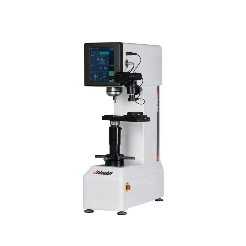
3.3 Digital (Closed-Loop) Rockwell Machine
Description: Replaces the deadweight beam with a load cell and a motorized actuator (ball screw or linear motor). A microprocessor controls the entire sequence.
Key differences from analog:
- No operator influence on loading rate (motor-controlled)
- Load is measured directly and corrected in real time (closed-loop control)
- Depth measured via LVDT (linear variable differential transformer) or optical encoder with 0.1 µm resolution
- Results displayed on a digital screen, not a dial
- Data can be exported (USB, Ethernet, RS-232) to LIMS or statistical software
Voordelen:
- Eliminates operator-to-operator variation
- Higher precision (repeatability ±0.3 HRC vs. ±0.8 HRC for analog)
- Automatic scale conversion (e.g., HRC to HB, HV)
- Built-in statistical process control (SPC) charts
Disadvantages:
- Higher cost (2–3× analog machines)
- Requires trained service for load cell calibration
- Electronics sensitive to dust, oil, and humidity